
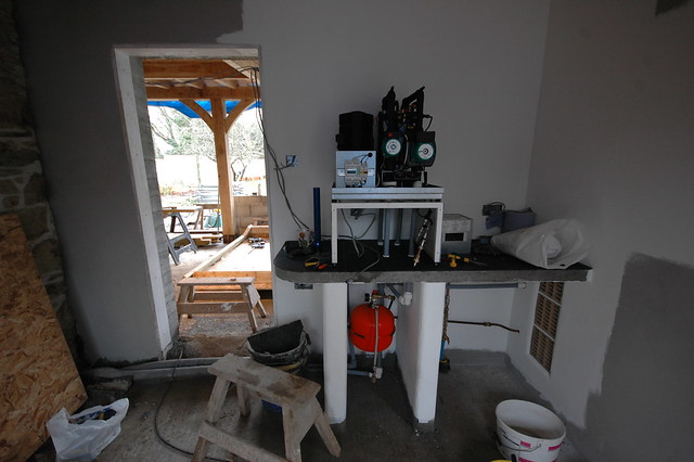
Heat pumps get mentioned here fairly regularly so I thought some of you might be interested in seeing the insides of mine. I've just reinstalled it so have a few pics of the guts.
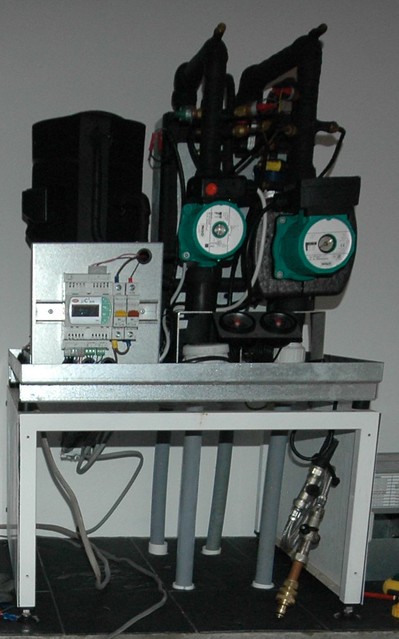
As you can see, there isn't an awful lot inside though all the sensors do make it look more complicated than it actually is.
The right hand two grey pipes coming out the bottom go outside and connect to 150m of pipe buried in the garden. The left hand two grey pipes lead to our underfloor heating system. The idea is we are going to transfer or "pump" the heat energy that is in the ground in our garden and put it into the floor of the house.
Part 1 is to get the heat out of the garden. This is achieved by the right hand green pump (just an ordinary central heating pump) which moves water through the pipes in the garden into the first heat exchanger (grey box just visible behind the pump) and then back out into the garden. The water from the garden typical arrives in the machine at 7 deg C, has heat energy removed by the heat exchanger (i.e. it is cooled) and leaves to go back out to the garden at 4 deg C. The pipes in the garden are 1.2m down where the temperature is typically around 10 deg C all year round. This is enough to reheat the water from 4 deg C to 7 deg C as it circulates in the pipe.
Part 2 is to get the gained heat into the floor in the house. The left hand green pump moves the water through the underfloor pipes in the house, through the second heat exchanger (again, grey box behind pump) and back out to the underfloor pipes. The water coming back from the underfloor typically returns at 30 deg C and has heat energy added to it by the heat exchanger (i.e. it gets hotter) and leaves to go back to the underfloor at 40 deg C.
As you can see, both loops are very similar in design, it is just the direction of heat transfer is different as are the temperatures involved.
Part 3 is the final bit and the section which most people have difficulty understanding. This is the compressor (or heat pump - big black lump top left) and its job is to move the heat from the right hand heat exchanger (and hence cool the outside ground loop) and put it into the left hand heat exchanger (and hence heat the inside underfloor loop). It achieves this by simply pumping a refrigerant through the left hand heat exchanger (1), then through a restriction in the pipe (2), then through the right hand heat exchanger (3) before returning to the compressor (4).
The following diagram for a fridge shows this process nicely. A heat pump and a fridge are basically identical in the way that they work.

The compressor does what it says on the can and compresses the refrigerant in the left hand section causing its pressure to rise. To keep Mr Boyle happy, increasing the pressure of a gas causes its temperature to rise, in our case by quite a lot - I don't have figures but it will be considerably higher than the 40 deg C we need and hence energy is transferred by the heat exchanger into the inside underfloor loop. The restriction in the pipe is designed such that only a small amount of gas can travel through it. This causes a large pressure differential and we end up with a very low pressure gas in the right hand loop. Again to keep Mr Boyle happy, the reduction in pressure causes a large temperature drop - this time to significantly below the 4 deg C we need and hence energy is removed via the heat exchanger from the outside ground loop.
As before, this is exactly the same principle as your fridge with the inside of the fridge being the same as the ground loop and the back of the fridge (the hot bit) being the same as the underfloor.
I guess that is probably far more information than you ever really needed to know...
As you can see, there isn't an awful lot inside though all the sensors do make it look more complicated than it actually is.
The right hand two grey pipes coming out the bottom go outside and connect to 150m of pipe buried in the garden. The left hand two grey pipes lead to our underfloor heating system. The idea is we are going to transfer or "pump" the heat energy that is in the ground in our garden and put it into the floor of the house.
Part 1 is to get the heat out of the garden. This is achieved by the right hand green pump (just an ordinary central heating pump) which moves water through the pipes in the garden into the first heat exchanger (grey box just visible behind the pump) and then back out into the garden. The water from the garden typical arrives in the machine at 7 deg C, has heat energy removed by the heat exchanger (i.e. it is cooled) and leaves to go back out to the garden at 4 deg C. The pipes in the garden are 1.2m down where the temperature is typically around 10 deg C all year round. This is enough to reheat the water from 4 deg C to 7 deg C as it circulates in the pipe.
Part 2 is to get the gained heat into the floor in the house. The left hand green pump moves the water through the underfloor pipes in the house, through the second heat exchanger (again, grey box behind pump) and back out to the underfloor pipes. The water coming back from the underfloor typically returns at 30 deg C and has heat energy added to it by the heat exchanger (i.e. it gets hotter) and leaves to go back to the underfloor at 40 deg C.
As you can see, both loops are very similar in design, it is just the direction of heat transfer is different as are the temperatures involved.
Part 3 is the final bit and the section which most people have difficulty understanding. This is the compressor (or heat pump - big black lump top left) and its job is to move the heat from the right hand heat exchanger (and hence cool the outside ground loop) and put it into the left hand heat exchanger (and hence heat the inside underfloor loop). It achieves this by simply pumping a refrigerant through the left hand heat exchanger (1), then through a restriction in the pipe (2), then through the right hand heat exchanger (3) before returning to the compressor (4).
The following diagram for a fridge shows this process nicely. A heat pump and a fridge are basically identical in the way that they work.
The compressor does what it says on the can and compresses the refrigerant in the left hand section causing its pressure to rise. To keep Mr Boyle happy, increasing the pressure of a gas causes its temperature to rise, in our case by quite a lot - I don't have figures but it will be considerably higher than the 40 deg C we need and hence energy is transferred by the heat exchanger into the inside underfloor loop. The restriction in the pipe is designed such that only a small amount of gas can travel through it. This causes a large pressure differential and we end up with a very low pressure gas in the right hand loop. Again to keep Mr Boyle happy, the reduction in pressure causes a large temperature drop - this time to significantly below the 4 deg C we need and hence energy is removed via the heat exchanger from the outside ground loop.
As before, this is exactly the same principle as your fridge with the inside of the fridge being the same as the ground loop and the back of the fridge (the hot bit) being the same as the underfloor.
I guess that is probably far more information than you ever really needed to know...


